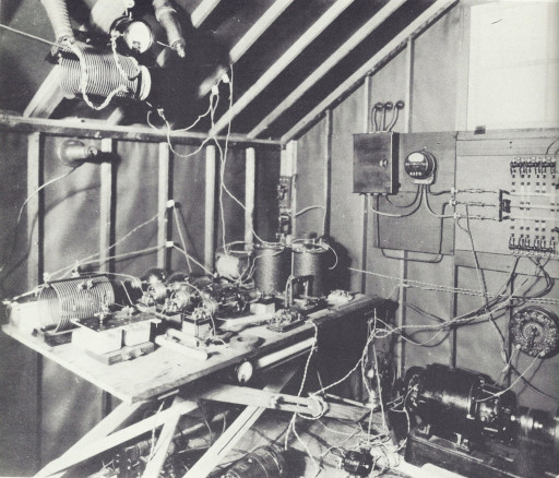
The 1BCG transmitter, as originally built, used two UV-204 Radiotron tubes in a self-excited, self-rectifying Colpitts oscillating circuit. It was rebuilt in the field into a master-oscillator, power-amplifier (MOPA) arrangement, to avoid the disadvantages of a self-excited oscillator and to produce a pure, steady CW signal. The single-204 oscillator was direct coupled to three more 204s in parallel in the amplifier. A motor-generator set supplied 2000 V dc for the plate voltage.

After the successful completion of the tests, the 1921 1BCG transmitter was removed to Columbia University for exhibition at a reading of a paper by the Radio Club of America. It is unknown what happened to the transmitter after that event.
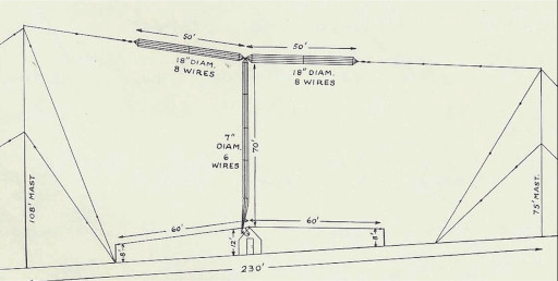
The antenna was a 100-foot horizontal cage flattop, made up in two sections each 50 feet long with eight #14 stranded phosphor-bronze wires that were equally spaced around 18-inch-diameter metal hoops and connected from the center point with a 70-foot cage downlead.
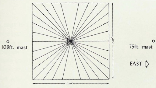
There was also a counterpoise consisting of 30 radial wires, each 60 feet long. The radials extended from a common central point, at a height of seven feet above the ground. To reduce resonance effects, the counterpoise had two equal fan-shaped halves, each with 15 wires.
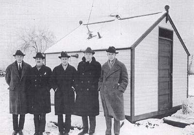
The 1BCG crew assembled at the shack. Left to right: Ernest V. Amy, John F. Grinan, George E. Burghard, Edwin H. Armstrong and Minton Cronkhite. Missing is Walker P. Inman.